I have recently been exploring some reciprocal force diagrams using Kangaroo.
From the 1869 paper by James Clerk Maxwell On reciprocal figures, frames and diagrams of forces :
…to construct the Polygon of Forces, by drawing in succession lines parallel and proportional to the different forces, each line beginning at the extremity of the last. If the forces acting at the point are in equilibrium, the polygon formed in this way will be a closed one.
Applications of such reciprocal force diagrams include the method of graphic statics, and also thrust network analysis (see Block and Ochsendorf 2007) for the form-finding of masonry vaults, in which the planar reciprocal network corresponds to the horizontal equilibrium of the nodes.
Kangaroo can generate structures in static equilibrium in a simple and intuitive way using dynamic relaxation. Once we have this equilibrium structure we can rearrange the force vectors to form such a reciprocal diagram. When the structure is modelled as a mesh I found there is a nice easy way to do this rearrangement also with Kangaroo: Scale the edges of the mesh so that their length corresponds to the force along that edge, then for each face, take the start points of its edges and just pull them together with attraction forces, but keeping the edge lengths and orientations fixed (ie allowing only pure translation). If the forces are balanced (which they will be if the simulation has stopped moving) then everything matches up as neatly closed polygons in the resulting reciprocal diagram. We can also optionally rotate the edges by 90° before pulling them together, which reduces the distance they have to move.


Grasshopper definition can be downloaded here
(Note that unlike the thrust network analysis approach which actually uses the reciprocal diagram as part of the process of generating the equilibrium structure, here I am just showing a way to generate such a reciprocal diagram from a structure after we have found its equilibrium. So in this case it is used not as an essential step, but as an alternative visual representation which I think can be quite revealing about the behaviour of the structure.)
In the special case where our structure has been form-found by treating the edges of a mesh as zero-rest-length springs of uniform stiffness, this generation of the reciprocal figure becomes even simpler still. Recall that the force in a spring is proportional to its extension relative to its rest length. If the rest length is zero, then the length is the extension, so the edge lengths already correspond to their forces and there is no need for any scaling step (another way of looking at this is that zero rest length springs of the same stiffness correspond to constant force-density elements).
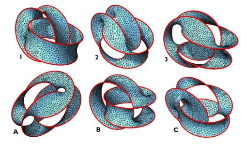
This lead me to thinking about the equivalent for tensile structures. If we relax the edges of a mesh with a non planar boundary, we can get a tensile network in space. Here because the only forces in the system are in the edges themselves (unlike the compression shell example, where there is also a vertical load vector on each point), we can actually form the reciprocal force diagram in 3d space without having to project to the plane. The reciprocal diagram is then another stable 3d tension structure of zero-rest-length springs.
(if you focus on a single edge, you will see that they do not rotate or change length, but only translate)
The word reciprocal is also used in a quite different context to refer to frame structures of mutually supporting elements, also sometimes called nexorades (which I explored a bit here).
As I was finding these reciprocal force diagrams, I noticed that as the lines were moving from the triangulated tension structure to its reciprocal (in the force diagram sense), the intermediate stages actually bore some resemblance to such reciprocal structures (in the nexorade sense). As shown the video above, by adding another force to keep the lines pulled onto each other while moving between the 2 forms, this can be emphasized even more, and means that the intermediate networks also form surfaces.

This suggested to me a connection to Bonnet rotations and associate, or adjoint families of minimal surfaces – see 1, 2, 3 for some more info on these (this also ties back in with my old interest in complex analysis).
The work of Pinkall and Polthier uses nonconforming triangulations for performing these Bonnet rotations, as well as describing the now widely used cotan weighting scheme for calculating discrete minimal surfaces. Kangaroo does now contain an option for such cotan weighted mesh smoothing, but this was not actually used in generating the mesh in the video above, because of how using uniformly weighted zero length springs simplifies the transition to the reciprocal diagram described earlier. However, because I have performed a remeshing so that the mesh triangles are all similar, the difference between these is greatly reduced.
Open question – what sort of linkages might allow a physical realization of these Bonnet rotations as an actual transformable structure?
Coming back to compression structures for a moment – in the last few years there has been something of a resurgence of interest in this area, and some great work not just from architecture and engineering departments, but also from the geometry processing/graphics side, and I think it is very exciting to see these disciplines coming together more.
Some recent papers that I have particularly enjoyed:
On the Equilibrium of Simplicial Masonry Structures by De Goes, Alliez, Owhadi, Desbrun
Computing Self-Supporting Surfaces by Regular Triangulation by Liu, Pan, Snyder, Wang, Guo
The use of a particle method for the modelling of isotropic membrane stress for the form finding of shell structures by Aish, Joyce, Malek, Williams
Form-finding with Polyhedral Meshes Made Simple by Tang, Sun, Gomes, Wallner, Pottmann
Design of Self-supporting Surfaces by Vouga, Hobinger, Wallner, Pottmann
Interactive Vault Design by Rippmann, Lachauer and Block
Designing Unreinforced Masonry Models by Panozzo, Block, Sorkine-Hornung
Weighted Triangulations for Geometry Processing by De Goes, Memari, Mullen, Desbrun
I should also mention that all of my examples above also make use of the remeshing tools I have been working on recently, for preparing the meshes before relaxation. Since the last time I wrote about dynamic remeshing here, I have made significant improvements to these tools (making use of the Plankton half-edge mesh library developed by Will Pearson and myself), and am finding many applications for them. Having meshes with well formed triangles of near equal edge lengths comes in very handy for all sorts of physical simulation and optimization (some more videos of this here: 1,2). I’m also now exploring more ways of actually carrying out the remeshing at the same time as the form-finding, and some of the papers above suggest to me some very interesting further possibilities in this direction.
Here is one example of using the dynamic remeshing coupled with surface smoothing for a very interactive approach to tensile form-finding:
…
Well, that turned into a longer post than I expected – lots of exciting stuff going on!
That’s about all from me for now, but I’d welcome any comments and discussion.
For some more on graphic statics see the Active Statics site by Simon Greenwold (who also wrote the particle-spring library used by the Cadenary tool, which was one of the early inspirations for Kangaroo), and also the eQuilibrium site from ETHZ.
For a lot more on things like thrust network analysis, force-density, dynamic relaxation and shells in general, the new book Shell Structures for Architecture: Form Finding and Optimization is now out. I had the pleasure of being one of the reviewers, and am very happy to see this book now in print – such a reference on these topics is very welcome, and I hope it will lead to even more interesting development and application of shells in architecture.